Subscribe

Saturday, October 17, 2009

CISCO : BGP Route Map Examples

BGP Route Map Examples


The following example shows how you can use route maps to modify incoming data from a neighbor. Any route received from 140.222.1.1 that matches the filter parameters set in autonomous system access list 200 will have its weight set to 200 and its local preference set to 250, and it will be accepted.

router bgp 100
!
 neighbor 140.222.1.1 route-map fix-weight in
 neighbor 140.222.1.1 remote-as 1
!
route-map fix-weight permit 10
 match as-path 200
 set local-preference 250
 set weight 200
!
ip as-path access-list 200 permit ^690$
ip as-path access-list 200 permit ^1800

In the following example, route map freddy marks all paths originating from autonomous system 690 with a Multi Exit Discriminator (MED) metric attribute of 127. The second permit clause is required so that routes not matching autonomous system path list 1 will still be sent to neighbor 1.1.1.1.

router bgp 100
 neighbor 1.1.1.1 route-map freddy out
!
ip as-path access-list 1 permit ^690_
ip as-path access-list 2 permit .*
!
route-map freddy permit 10
 match as-path 1
 set metric 127
!
route-map freddy permit 20
 match as-path 2

The following example shows how you can use route maps to modify incoming data from the IP forwarding table:

router bgp 100
 redistribute igrp 109 route-map igrp2bgp
!
route-map igrp2bgp
 match ip address 1
 set local-preference 25
 set metric 127
 set weight 30000
 set next-hop 192.92.68.24
 set origin igp
!
access-list 1 permit 131.108.0.0 0.0.255.255
access-list 1 permit 160.89.0.0 0.0.255.255
access-list 1 permit 198.112.0.0 0.0.127.255

It is proper behavior to not accept any autonomous system path not matching the match clause of the route map. This means that you will not set the metric and the Cisco IOS software will not accept the route. However, you can configure the software to accept autonomous system paths not matched in the match clause of the route map command by using multiple maps of the same name, some without accompanying set commands.

route-map fnord permit 10
 match as-path 1
 set local-preference 5
!
route-map fnord permit 20
 match as-path 2

The following example shows how you can use route maps in a reverse operation to set the route tag (as defined by the BGP/OSPF interaction document, RFC 1403) when exporting routes from BGP into the main IP routing table:

router bgp 100
 table-map set_ospf_tag
!
route-map set_ospf_tag
 match as-path 1
 set automatic-tag
!
ip as-path access-list 1 permit .*

In the following example, the route map called set-as-path is applied to outbound updates to the neighbor 200.69.232.70. The route map will prepend the autonomous system path "100 100" to routes that pass access list 1. The second part of the route map is to permit the advertisement of other routes.

router bgp 100
 network 171.60.0.0
 network 172.60.0.0
 neighbor 200.69.232.70 remote-as 200
 neighbor 200.69.232.70 route-map set-as-path out
!
route-map set-as-path 10 permit
 match address 1
 set as-path prepend 100 100
!
route-map set-as-path 20 permit
 match address 2
!
access-list 1 permit 171.60.0.0 0.0.255.255
access-list 1 permit 172.60.0.0 0.0.255.255
!
access-list 2 permit 0.0.0.0 255.255.255.255

Inbound route-maps could do prefix-based matching and set various parameters of the update. Inbound prefix matching is available in addition to as-path and community-list matching. In the following example, the set local preference command sets the local preference of the inbound prefix 140.10.0.0/16 to 120.

!
router bgp 100
 network 131.108.0.0
 neighbor 131.108.1.1 remote-as 200
 neighbor 131.108.1.1 route-map set-local-pref in !
route-map set-local-pref permit 10
 match ip address 2
 set local preference 120
!
route-map set-local-pref permit 20
!
access-list 2 permit 140.10.0.0 0.0.255.255 access-list 2 deny any


Source link : http://www.cisco.com/en/US/docs/ios/11_3/np1/configuration/guide/1cbgp.html#wp3020

Thursday, September 10, 2009

NETWORK TOPOLOGY


NETWORK TOPOLOGY


What is a Topology ?

The physical topology of a network refers to the configuration of cables, computers, and other peripherals. Physical topology should not be confused with logical topology which is the method used to pass information between workstations. Logical topology was discussed in the Protocol chapter .

Main Types of Physical Topologies

The following sections discuss the physical topologies used in networks and other related topics.

  • Linear Bus
  • Star
  • Star-Wired Ring
  • Tree
  • Considerations When Choosing a Topology
  • Summary Chart

Linear Bus

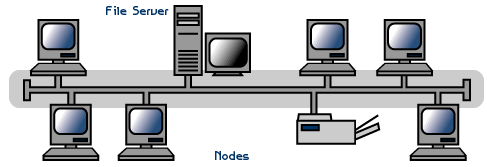
A linear bus topology consists of a main run of cable with a terminator at each end (See fig. 1). All nodes (file server, workstations, and peripherals) are connected to the linear cable. Ethernet and LocalTalk networks use a linear bus topology.


Fig. 1. Linear Bus topology

Advantages of a Linear Bus Topology

  • Easy to connect a computer or peripheral to a linear bus.
  • Requires less cable length than a star topology.

Disadvantages of a Linear Bus Topology

  • Entire network shuts down if there is a break in the main cable.
  • Terminators are required at both ends of the backbone cable.
  • Difficult to identify the problem if the entire network shuts down.
  • Not meant to be used as a stand-alone solution in a large building.

Star

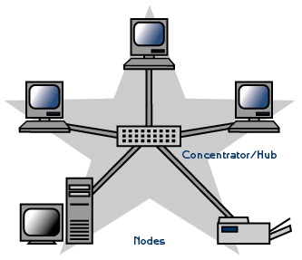
A star topology is designed with each node (file server, workstations, and peripherals) connected directly to a central network hub or concentrator (See fig. 2).

Data on a star network passes through the hub or concentrator before continuing to its destination. The hub or concentrator manages and controls all functions of the network. It also acts as a repeater for the data flow. This configuration is common with twisted pair cable; however, it can also be used with coaxial cable or fiber optic cable.


Fig. 2. Star topology

Advantages of a Star Topology

  • Easy to install and wire.
  • No disruptions to the network then connecting or removing devices.
  • Easy to detect faults and to remove parts.

Disadvantages of a Star Topology

  • Requires more cable length than a linear topology.
  • If the hub or concentrator fails, nodes attached are disabled.
  • More expensive than linear bus topologies because of the cost of the concentrators.

The protocols used with star configurations are usually Ethernet or LocalTalk. Token Ring uses a similar topology, called the star-wired ring.

Star-Wired Ring

A star-wired ring topology may appear (externally) to be the same as a star topology. Internally, the MAU (multistation access unit) of a star-wired ring contains wiring that allows information to pass from one device to another in a circle or ring (See fig. 3). The Token Ring protocol uses a star-wired ring topology.

Tree

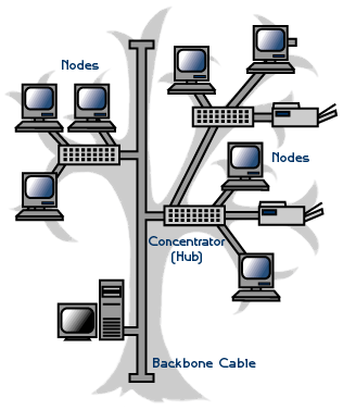
A tree topology combines characteristics of linear bus and star topologies. It consists of groups of star-configured workstations connected to a linear bus backbone cable (See fig. 4). Tree topologies allow for the expansion of an existing network, and enable schools to configure a network to meet their needs.


Fig. 4. Tree topology

Advantages of a Tree Topology

  • Point-to-point wiring for individual segments.
  • Supported by several hardware and software venders.

Disadvantages of a Tree Topology

  • Overall length of each segment is limited by the type of cabling used.
  • If the backbone line breaks, the entire segment goes down.
  • More difficult to configure and wire than other topologies.

5-4-3 Rule

A consideration in setting up a tree topology using Ethernet protocol is the 5-4-3 rule. One aspect of the Ethernet protocol requires that a signal sent out on the network cable reach every part of the network within a specified length of time. Each concentrator or repeater that a signal goes through adds a small amount of time. This leads to the rule that between any two nodes on the network there can only be a maximum of 5 segments, connected through 4 repeaters/concentrators. In addition, only 3 of the segments may be populated (trunk) segments if they are made of coaxial cable. A populated segment is one which has one or more nodes attached to it . In Figure 4, the 5-4-3 rule is adhered to. The furthest two nodes on the network have 4 segments and 3 repeaters/concentrators between them.

This rule does not apply to other network protocols or Ethernet networks where all fiber optic cabling or a combination of a fiber backbone with UTP cabling is used. If there is a combination of fiber optic backbone and UTP cabling, the rule is simply translated to 7-6-5 rule.

Considerations When Choosing a Topology:

  • Money. A linear bus network may be the least expensive way to install a network; you do not have to purchase concentrators.
  • Length of cable needed. The linear bus network uses shorter lengths of cable.
  • Future growth. With a star topology, expanding a network is easily done by adding another concentrator.
  • Cable type. The most common cable in schools is unshielded twisted pair, which is most often used with star topologies.

Summary Chart:

Physical Topology Common Cable Common Protocol
Linear Bus Twisted Pair
Coaxial
Fiber
Ethernet
LocalTalk
Star Twisted Pair
Fiber
Ethernet
LocalTalk
Star-Wired Ring Twisted Pair Token Ring
Tree Twisted Pair
Coaxial
Fiber
Ethernet


Another Topology in network


OSI LAYER


The 7 Layers of the OSI Model

Last updated: March 03, 2008


The OSI, or Open System Interconnection, model defines a networking framework for implementing protocols in seven layers. Control is passed from one layer to the next, starting at the application layer in one station, proceeding to the bottom layer, over the channel to the next station and back up the hierarchy.


Application
(Layer 7)
This layer supports application and end-user processes. Communication partners are identified, quality of service is identified, user authentication and privacy are considered, and any constraints on data syntax are identified. Everything at this layer is application-specific. This layer provides application services for file transfers, e-mail, and other network software services. Telnet and FTP are applications that exist entirely in the application level. Tiered application architectures are part of this layer.
Presentation
(Layer 6)
This layer provides independence from differences in data representation (e.g., encryption) by translating from application to network format, and vice versa. The presentation layer works to transform data into the form that the application layer can accept. This layer formats and encrypts data to be sent across a network, providing freedom from compatibility problems. It is sometimes called the syntax layer.
Session
(Layer 5)
This layer establishes, manages and terminates connections between applications. The session layer sets up, coordinates, and terminates conversations, exchanges, and dialogues between the applications at each end. It deals with session and connection coordination.
Transport
(Layer 4)
This layer provides transparent transfer of data between end systems, or hosts, and is responsible for end-to-end error recovery and flow control. It ensures complete data transfer.
Network
(Layer 3)
This layer provides switching and routing technologies, creating logical paths, known as virtual circuits, for transmitting data from node to node. Routing and forwarding are functions of this layer, as well as addressing, internetworking, error handling, congestion control and packet sequencing.
Data Link
(Layer 2)
At this layer, data packets are encoded and decoded into bits. It furnishes transmission protocol knowledge and management and handles errors in the physical layer, flow control and frame synchronization. The data link layer is divided into two sub layers: The Media Access Control (MAC) layer and the Logical Link Control (LLC) layer. The MAC sub layer controls how a computer on the network gains access to the data and permission to transmit it. The LLC layer controls frame synchronization, flow control and error checking.
Physical
(Layer 1)
This layer conveys the bit stream - electrical impulse, light or radio signal -- through the network at the electrical and mechanical level. It provides the hardware means of sending and receiving data on a carrier, including defining cables, cards and physical aspects. Fast Ethernet, RS232, and ATM are protocols with physical layer components.


RECOMMENDED READING:


Image courtesy of The Abdus Salam International Centre for Theoretical Physics.

Wednesday, September 2, 2009

Win Server 2003 : Active Directory >> Create the first Win Server 2003 Domain Controller


Creating the first

Windows Server 2003 Domain Controller in a domain


Preface:

One of the greatest features of Windows Server 2003 is its ability to be a Domain Controller (DC). The features of a domain extend further than this tutorial ever could, but some of its most well known features are its ability to store user names and passwords on a central computer (the Domain Controller) or computers (several Domain Controllers). In this tutorial we will cover the "promoting" (or creating) of the first DC in a domain. This will include DNS installation, because without DNS the client computers wouldn't know who the DC is. You can host DNS on a different server, but we'll only deal with the basics.

Method:

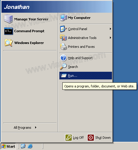
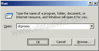
Click Start -> Run...

Type "dcpromo" and click "OK"

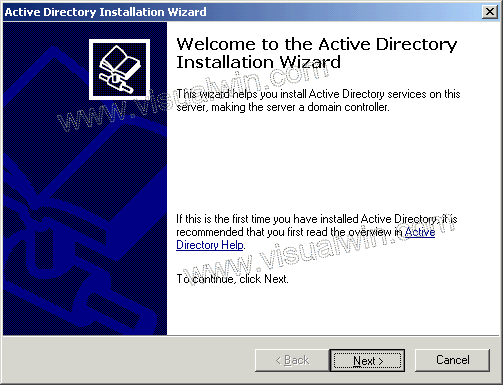
You will see the first window of the wizard. As it suggests, I suggest reading the help associated with Active Directory. After this, click "Next"

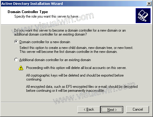
Click "Next" on the compatibility window, and in the next window keep the default option of "Domain Controller for a new domain" selected, and click "Next"

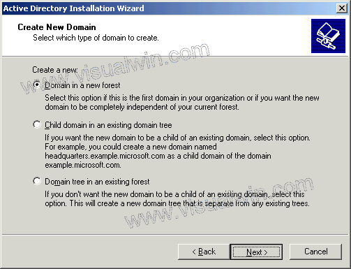
In this tutorial we will create a domain in a new forest, because it is the first DC, so keep that option selected

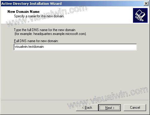
Now we have to think of a name for our domain. If you own a web domain like "visualwin.com", you can use it, but it isn't suggested because computers inside of your domain may not be able to reach the company website. Active Directory domains don't need to be "real" domains like the one above - they can be anything you wish. So here I will create "visualwin.testdomain"

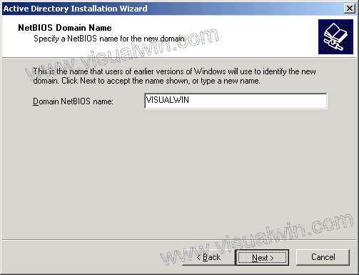
Now in order to keep things simple, we will use the first part of our domain ("visualwin"), which is the default selection, as the NetBIOS name of the domain

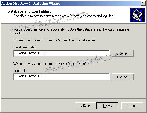
The next dialog suggests storing the AD database and log on separate hard disks, and so do I, but for this tutorial I'll just keep the defaults

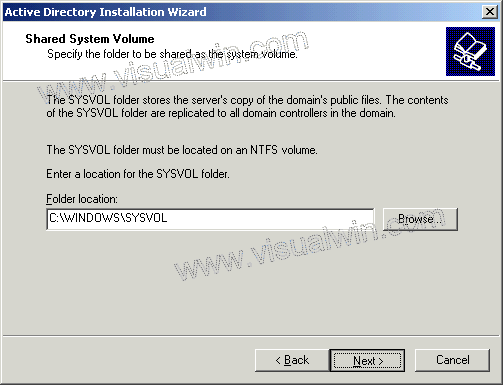
The SYSVOL folder is a public share, where things like .MSI software packages can be kept when you will distribute packages (as I said, AD has a lot of different features). Once again, I will keep the default selection but it can be changed if you wish to use the space of another drive

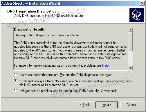
Now we will get a message that basically says that you will need a DNS server in order for everything to work the way we want it (i.e., our "visualwin.testdomain" to be reachable). As I mentioned earlier, we will install the DNS server on this machine as well, but it can be installed elsewhere. So keep the default selection of "Install and configure", and click "Next"

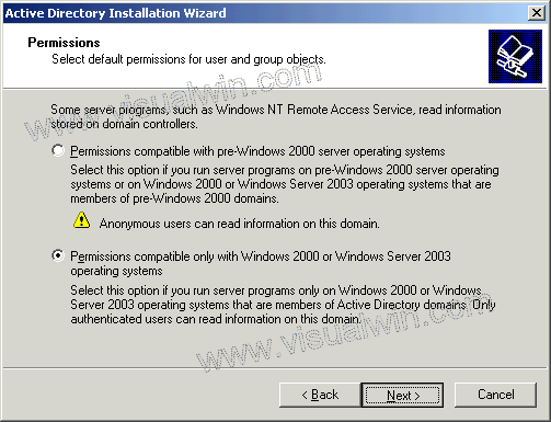
Because, after all, this is a Windows Server 2003 tutorial website, we'll assume there are no pre-Windows 2000 servers that will be accessing this domain, so keep the default of "Permissions compatible only with Windows 2000 or Windows Server 2003 operating systems" and click "Next"
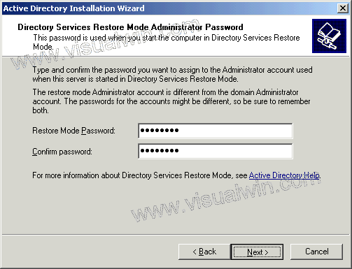
The restore mode password is the single password that all administrators hope to never use, however they should also never forget it because this is the single password that might save a failed server. Make sure it's easy to remember but difficult to guess

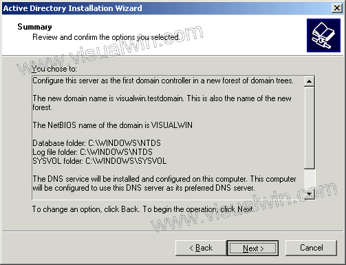
Now we will see a summary of what will happen. Make sure it's all correct because changing it afterwards can prove to be difficult

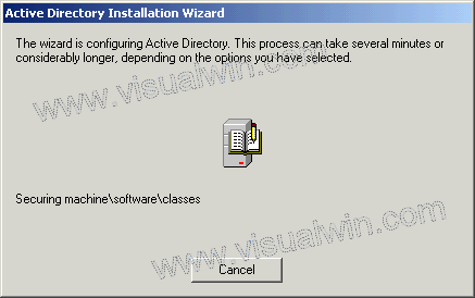
After the previous next was clicked, the actual process occurs. This can take several minutes. It's likely that you will be prompted for your Windows Server 2003 CD (for DNS) so have it handy

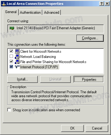
If your computer has a dynamically assigned address (from DHCP) you will be prompted to give it a static IP address. Click ok, and then in the Local Area Connection properties, click "Internet Protocol (TCP/IP)" and then "Properties"

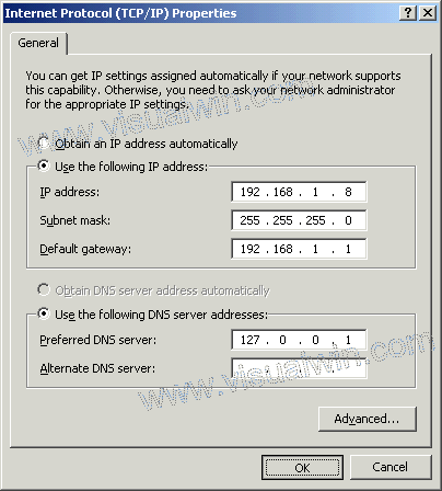
In the next window select "Use the following IP address" and select the information that you will use for your domain (and 127.0.0.1 for the primary DNS, because your computer will host DNS. I still suggest setting up an alternate as well.) Click "OK" and then "Close" on the next window

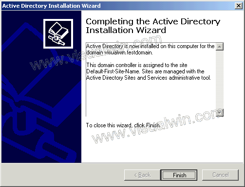
And after a while you will see

And we're finished. You may also want to see the other Active Directory tutorials on the main page.

Copyright ©2002-2008 Jonathan Maltz.

Tuesday, September 1, 2009

Win Server 2003 : Active Directory : Adding Windows XP to Win Server 2003


Adding a Windows XP computer to a Windows Server 2003 domain


Preface:

This is basically the same procedure as the Windows 2000 tutorial. Some things to note about adding a Windows XP computer to a domain are the following:

  • You need Windows XP Professional to join a XP computer to a domain. Home can't be used fully for this

  • You will loose the "fancy" log on screen and you will receive the "classic" log on screen instead. This is for security and cannot be changed, unless you revert to workgroup mode

  • You will loose the "Fast User Switching". This cannot be restored, except by reverting back to workgroup mode.

Method:

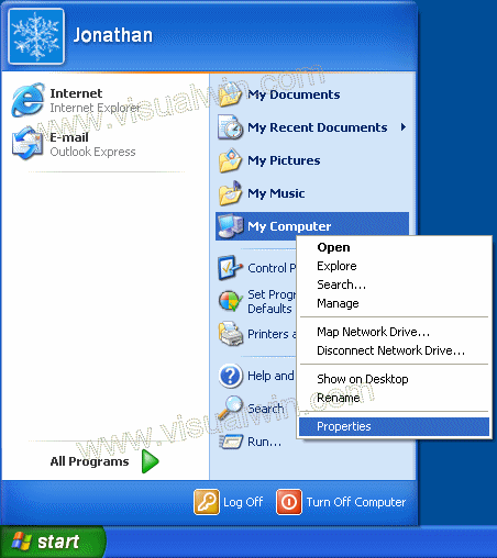
Click Start, right click "My Computer" and click "Properties"

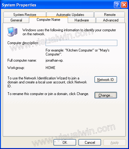
Go to the "Computer Name" tab and click "Change..."

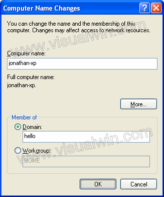
Select the "Domain" radio button then put in your domain name, not including the . extension (in my example I used the domain "hello.test" but when joining the computer to a domain, I will only type "hello")

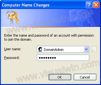
Press "OK". Then you will be presented with a user name and password prompt. Enter the user name and password of a Domain Administrator

Press "OK" and after a minute or two you will receive a message welcoming you to the domain. Then you will receive a message telling you that a reboot is required, click "OK" to that, and the properties window. Then click "Yes" when you are prompted to reboot.

And we're finished. You have just learnt how to add a Windows XP computer to a Windows Server 2003 domain

Additive:

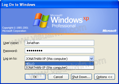
After the XP computer boots to Control-Alt-Delete you may need to change it from logging onto itself (which will use the local info) to logging onto the domain. To do this, press Ctrl-Alt-Del, then the "Options >>>" button on the log on screen. Then select the domain from the drop-down box

After that you can log on using domain credentials

Copyright ©2002-2008 Jonathan Maltz.

Win Server 2003 : Active Directory >> Adding a computer


Adding a computer to Active Directory


Preface:

Earlier, I showed you how to add users to your Active Directory domain. This tutorial will focus on how to add computers. This step is not "really" necessary for workstation computers - at least, I was able to add a Windows XP machine to my domain without adding the computer name first. This is section is really for looking at which computers join, and allow other servers to join as DC's, etc. I will show you how to add the computer using "Active Directory Users and Computers", then in other tutorials, I will demonstrate how to add a Windows 2000 computer and Windows XP computer to this domain.

Update:

Brian Desmond (Windows Server MVP) emailed me with the following information on why someone might want to add a computer to AD manually:

"By default a computer will get dumped in the Computers container, unless a Windows 2003 Native Mode Domain is inplace, and redircomp has been run to change this. Precreating computer accounts in OUs will ensure that when the unit is joined, it is in the correct OU, which guarantees policy consistency, and other administrative things. One can also specify who can reset the machine’s password. This will allow an admin to create an account for a computer, and let a normal user join the machine with their credentials."

Method:

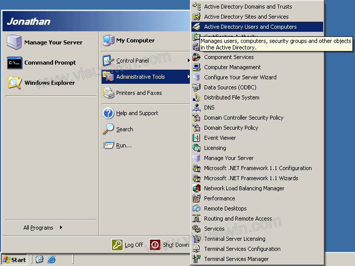
Click Start, highlight "Administrative Tools" and select "Active Directory Users and Computers"

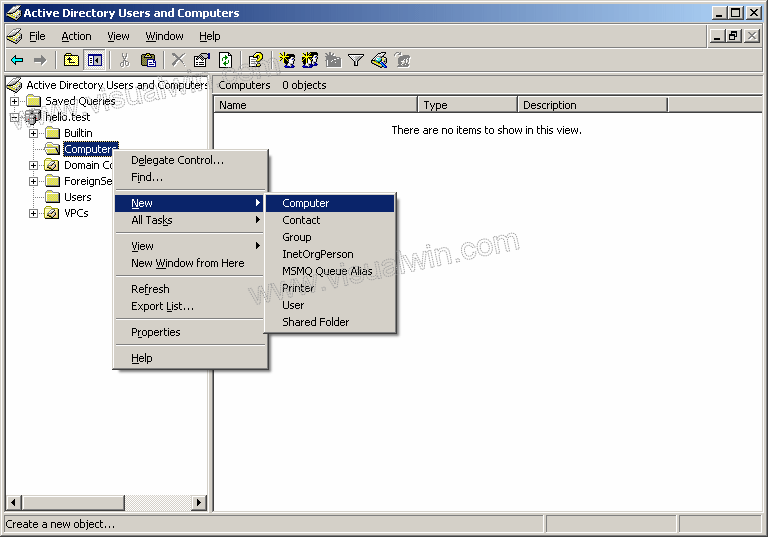
Expand your domain name, and right-click "Computers", highlight "New" then click "Computer"

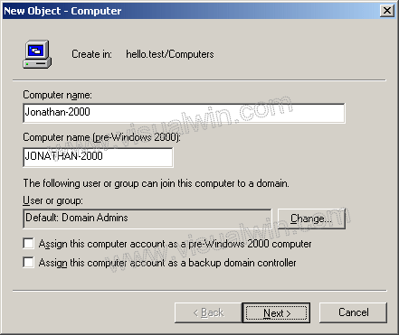
In this dialog we have to type the name of the computer we want to add

In the next dialog just click "Next", then you will see a final report of what will be added, and you can click "Finish".

And, we're done!

Copyright ©2002-2008 Jonathan Maltz.

Win Server 2003 : Active Directory >> Adding users


Adding users to Active Directory


Preface:

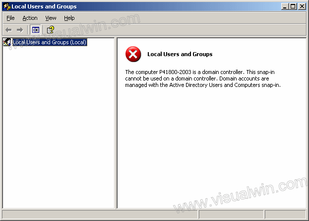
As you know, if you try to add AD users using lusrmgr.msc you will receive the following error:

And since I cover creating a local user (lusr) I thought it would only be right to cover creating an Active Directory user.

Method:

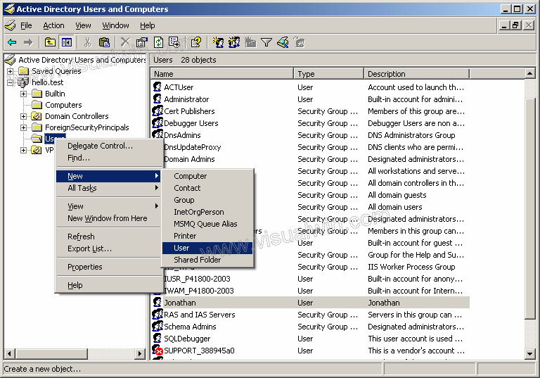
Click Start, highlight "Administrative Tools" and select "Active Directory Users and Computers"

Now, expand your domain name on the left side, and go to the bottom where it says "Users". Once you click on that, you will see all of the automatically created users, you will also see all of the users you made before you ran dcpromo - that's because they all stay through the promotion to DC. Anyway, to add a user, you can either right click the "Users" folder on the left side, or the blank area on the right side, and highlight "New" then click "User"

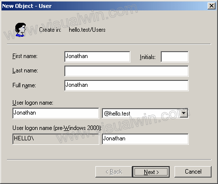
In the next dialog we can set the user's First name, Last name and various other pieces of information, including their log-on name, and domain to which we want to add them

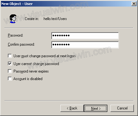
After clicking "Next" you are presented with the password-settings screen. You can set the user's password and then have them change it on their first log-on by selecting "User must change password at next logon". But in this tutorial, I will set it as their password, and not allow them to ever change it without asking me (the administrator) to change it for them

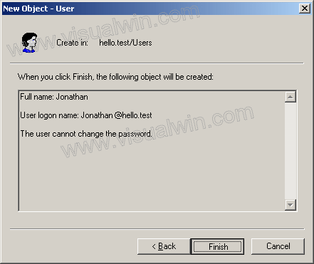
In the next dialog, we get a summary of the user to be created. Click "Finish" and the user has been created

And we're finished! Now, you might want to check out the tutorial on how to add a computer to Active Directory, that will help you get the full benefits of AD.

Copyright ©2002-2008 Jonathan Maltz. For trademark/copyright information

Monday, August 31, 2009

Download Cisco IOS Image

Download Cisco IOS Image Using the Boot Image from a Trivial File Transfer Protocol (TFTP) Server

There is only one way to install an image on the 2500, 3000, AS5100, or uBR900 Series Routers if the main Cisco IOS software has been deleted or corrupted. You must use its boot image.

Since you have already determined that the cause of the router booting up in ROMmon is not due to the configuration register value, the only option available for recovery is to re-install or upgrade the Cisco IOS software from a TFTP server using the built-in boot image (Rx-boot) in ROM.

To get into the Rx-boot mode or boot image, do the following:

  1. If the rommon prompt is "rommon # >", type:

    rommon 1 > confreg 0x2101

    You must reset or power cycle the router for the new configuration to take effect:

    rommon 2>reset
    System Bootstrap, Version 12.0(6r)T3, RELEASE SOFTWARE (fc1) Copyright (c) 1999 by cisco Systems, Inc.
    UBR924 platform with 16384 Kbytes of main memory.......................
  2. If the rommon prompt is ">", type:

    >o/r 0x2101         
    >i
    System Bootstrap, Version 11.0(10c)XB2, RELEASE SOFTWARE
    Copyright (c) 1986-1994 by cisco Systems
    2500 processor with 16384 Kbytes of main memory

    Restricted Rights Legend

    Use, duplication, or ................


    !--- Output suppressed


    .............16384K bytes of processor board System flash (Read/Write)

    Press RETURN to get started!

    hostname(boot)>

    Notice that the prompt is now "router (boot)>", confirming that the router has booted up using the boot image.

    Note: If the router boots up in ROMmon again, most likely the boot image is corrupt or missing and the only way to recover is by replacing the processor board System Flash or hardware.

  3. The next step is to upgrade the Cisco IOS software as follows:

    hostname(boot)>enable
    hostname(boot)#copy tftp flash
    System flash directory:
    File Length Name/status

    1 2416128 c2500-is-l.123-1a.bin [invalid checksum]

    [2416192 bytes used, 14361024 available, 16777216 total]
    Address or name of remote host [255.255.255.255]? 172.16.1.2
    Source file name? c2500-is-l.123-1a.bin
    Destination file name [c2500-is-l.123-1a.bin]?
    Accessing file 'c2500-is-l.123-1a.bin' on 172.16.1.2...
    Loading c2500-is-l.123-1a.bin from 172.16.1.2 (via Ethernet0): ! [OK]

    Erase flash device before writing? [confirm]


    !--- Press Enter to confirm


    Flash contains files. Are you sure you want to erase? [confirm]


    !--- Press Enter to confirm


    Copy 'c2500-is-l.123-1a.bin' from server
    as 'c2500-is-l.123-1a.bin' into Flash WITH erase? [yes/no]yes
    Erasing device... eeeeeeeeeeeeeeeeeeeeeeeeeeeeeeeeeeeeeeeeeeeeeeeeeeeeeeeeeeeeee
    ee ...erased
    Loading c2500-is-l.123-1a.bin from 172.16.1.2 (via Ethernet0): !!!!!!!!!!!!!!!!!
    !!!!!!!!!!!!!!!!!!!!!!!!!!!!!!!!!!!!!!!!!!!!!!!!!!!!!!!!!!!!!!!!!!!!!!!!!!!!!!!!


    !--- Output suppressed


    !!!!!!!!!!!!!!!!!!!!!!!!!!!!!!!!!!!!!!!!!!!!!!!!!!!!!!!!!!!!!!!!!!!!!!!!!!!!!!!!
    !!!!!!!!!!!!!!!!!!!!!!!!!!!!!!!!!!!!!!!!!!!!!!
    [OK - 16294764/16777216 bytes]

    Verifying checksum... OK (0x96AA)
    Flash copy took 0:08:23 [hh:mm:ss]
    hostname(boot)#
  4. Use the show flash command to verify the newly-loaded Cisco IOS image version.

    hostname(boot)#show flash

    System flash directory:
    File Length Name/status
    1 16294764 c2500-is-l.123-1a.bin
    [16294828 bytes used, 482388 available, 16777216 total]
    16384K bytes of processor board System flash (Read/Write)
    hostname(boot)#
  5. After successfully copying the Cisco IOS image to the router, make sure that you change the configuration register back to 0x2102 and reload the router to boot from the Cisco IOS image.

    hostname(boot)(config)#config-register 0x2102
    hostname(boot)#reload
    System configuration has been modified. Save? [yes/no]: no
    Proceed with reload? [confirm]


    !--- Press Enter to confirm


    *Mar 1 00:12:58.463: %SYS-5-RELOAD: Reload requested
    System Bootstrap, Version 11.0(10c)XB2, PLATFORM SPECIFIC RELEASE SOFTWARE (fc1)

    Copyright (c) 1986-2003 by cisco Systems
    2500 processor with 14336 Kbytes of main memory

    F3: 15405292+889440+952984 at 0x3000060


    !--- Output suppressed


    Press RETURN to get started!

    hostname>
  6. Use the show version command to verify the configuration register value and the newly-loaded Cisco IOS image version.

    hostname>show version
    Cisco Internetwork Operating System Software
    IOS (tm) 2500 Software (C2500-IS-L), Version 12.3(1a), RELEASE SOFTWARE (fc1)
    Copyright (c) 1986-2003 by cisco Systems, Inc.
    Compiled Fri 06-Jun-03 07:46 by dchih
    Image text-base: 0x0307F6E8, data-base: 0x00001000

    ROM: System Bootstrap, Version 11.0(10c)XB2, PLATFORM SPECIFIC RELEASE SOFTWARE
    (fc1)
    BOOTLDR: 3000 Bootstrap Software (IGS-BOOT-R), Version 11.0(10c)XB2, PLATFORM SP
    ECIFIC RELEASE SOFTWARE (fc1)

    Router uptime is 2 minutes
    System returned to ROM by reload
    System image file is "flash:c2500-is-l.123-1a.bin"

    cisco 2500 (68030) processor (revision L) with 14336K/2048K bytes of memory.
    Processor board ID 13587050, with hardware revision 00000000
    Bridging software.
    X.25 software, Version 3.0.0.
    2 Ethernet/IEEE 802.3 interface(s)
    2 Serial network interface(s)
    32K bytes of non-volatile configuration memory.
    16384K bytes of processor board System flash (Read ONLY)

    Configuration register is 0x2102

Password Recovery Cisco 2500

Verify the Configuration Register Value

The first thing that needs to be investigated is why the router is booting up in ROMmon mode (indicated by the "rommon # >" or ">" prompt). Determine whether the cause is due to the change of the configuration register value, or a corrupted Cisco IOS software image.

If the router has a valid Cisco IOS software image, then simply changing the configuration value register to 0x2102 will recover the router. The procedure for this is explained below.

  1. If the ROMmon prompt is ">", type the following at the ROMmon prompt:

    >o/r 0x2102      
    >i
    System Bootstrap, Version 11.0(10c)XB2, RELEASE SOFTWARE
    Copyright (c) 1986-2003 by cisco Systems
    2500 processor with 16384 Kbytes of main memory

    F3: 10021772+224116+562960 at 0x3000060

    Restricted Rights Legend

    Use, duplication,............................
  2. If the ROMmon prompt is "rommon #>", type the following at the prompt:

    rommon 1> confreg 0x2102

    You must reset or power cycle the router for the new configuration to take effect:

    rommon 2> reset
    System Bootstrap, Version 12.0(6r)T3, RELEASE SOFTWARE (fc1)
    Copyright (c) 1999 by cisco Systems, Inc.
    UBR924 platform with 16384 Kbytes of main memory.......................

    If the router boots up successfully, then the cause was a configuration register value issue.

If the router boots up in ROMmon again, proceed to Download Cisco IOS Image Using the Boot Image from a Trivial File Transfer Protocol (TFTP) Server.